
|
|
General HydroStatics
Ship Stability Software |
|
Command of the Week
(New or interesting aspects of GHS that you may not know about) |
|
WIND Moment Methods (review)
(Requires GHS version 18.78C or later with CG) |
|
There are three methods to choose from when applying heeling moments due to wind.
The original method is generally referred to as the lateral plane method. It takes lateral projections (min & max V for all points on each station) of all components (without consideration of shielding) and applies wind pressure at the center of each component. This method is only available for beam winds. STATUS LPLANE always uses this method, as do system variables LPA1, LPA2, HCP2, and LPAARM.
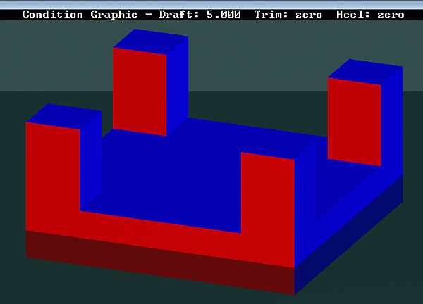
The band method was introduced in version in 10.16, which translates to roughly April 2006. It calculates the wind force by projecting the area of each component within a part onto a single set of horizontal bands. Any overlapping areas in each band are ignored which provides for the shielding effect. The wind pressure at the center of each band is applied so there might be small, unavoidable differences compared to the lateral plane method if a wind gradient is used as is the case with the usual WIND knots. The band method respects any AXIS making it the de facto choice for MODU vessels for many years. The panel method was introduced in 2023. As mentioned in COW321, instead of using the station points, the surfaces are used to calculate areas, centroids, pressures, normal vectors, forces, and moments. Where the shielding in the band method depends on how the geometry is organized within the part-component hierarchy, and several modifying HMMT parameters, shielding in the panel method is determined simply by distances between the panels. As you will see, in some cases the three methods produce identical results. First, we'll need a geometry file to use for comparison. If you want to play along at home, here is the run file that generates the geometry shown below by DISPLAY STATUS WIND. |
|
|
The four towers are modeled as separate parts in the model so that they don't shield each other when using default HMMT /BAND settings.
To generate a HMMT REPORT for each method, we used the following macro which takes the method as the first parameter. |
|
`...read geometry and establish loading condition
wind (pressure) .01 macro go hmmt wind %1 heel 0 solve trim hmmt report / .go "" .go /band .go /panel |
|
The results below present the upright wind heeling moment for the three methods. |

|
| For these results, the geometry file, floating condition, and even the uniform pressure have been selected to eliminate the differences between the calculations. It's no surprise then that all three produce the same heeling moment. |
|
Questions, comments, or requests?
Contact Creative Systems, Inc. USA phone: 360-385-6212 Fax: 360-385-6213 Office hours: 7:00 am - 4:00 pm Pacific Time, Monday - Friday Mailing address: PO Box 1910 Port Townsend, WA 98368 USA Click here for an index to this and previous COWs |